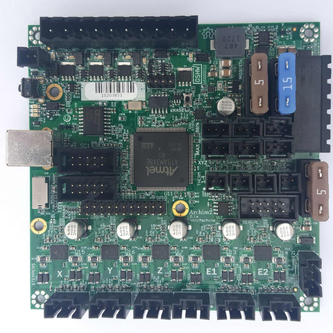
Archim2
UltiMachine
From $ 249.00
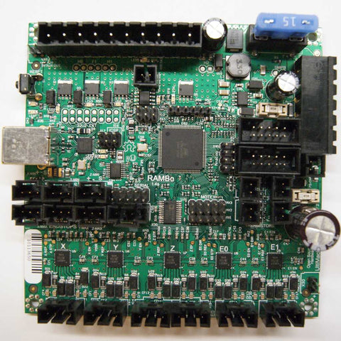
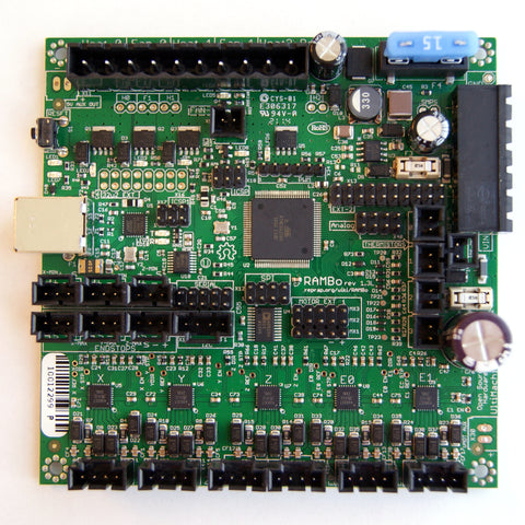
RAMBo 1.4
RAMBo 1.3
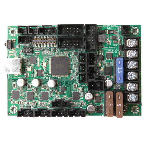
Einsy Rambo 1.2
From $ 165.00
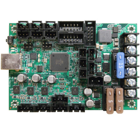
Einsy Retro
From $ 110.00
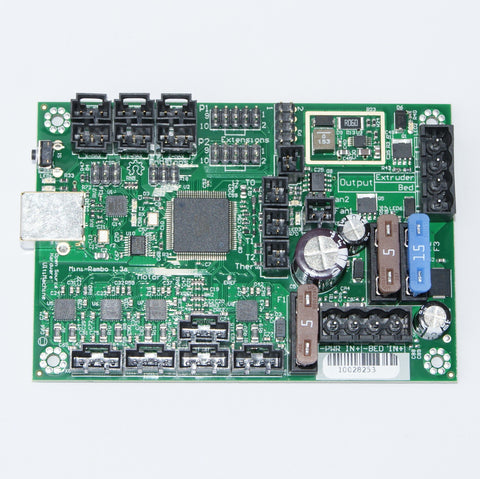
Mini-Rambo 1.3
From $ 137.00
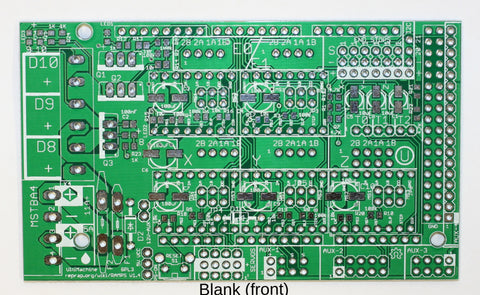
RAMPS - PCB Shield (No Kit)
ultimachine.com
From $ 10.00
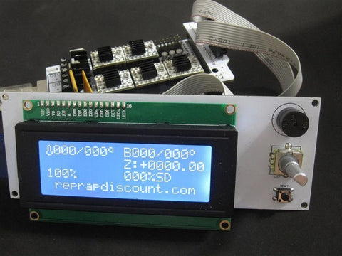
LCD Smart Controller Kit from Reprapdiscount
Reprapdiscount
From $ 45.00
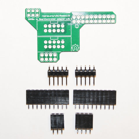
LCD Smart Controller Adapter Board Kit for RAMBo
From $ 5.00
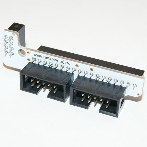
LCD Smart Controller Adapter Board for RAMPS
$ 10.00
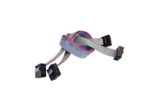
LCD Smart Controller Flat Cables from Reprapdiscount
$ 2.25
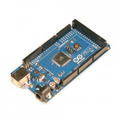
Arduino MEGA 2560 R3
$ 65.00
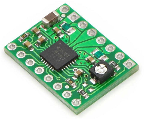
Pololu A4988 Stepper Driver Kit
From $ 13.00
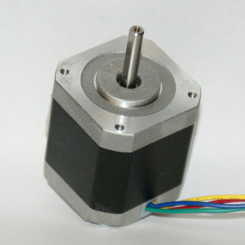
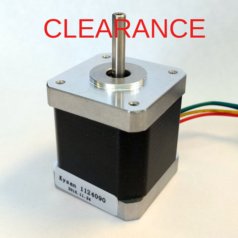
Kysan 1124090 Nema 17 Stepper Motor
Kysan Electronics
$ 14.50
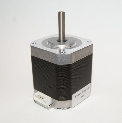
Kysan 1124141 Nema 17 Stepper Motor, No Wire Harness
$ 16.50
Kysan 1124090 Nema 17 Stepper Motor *Wrong Casing* CLEARANCE
$ 12.50
Kysan 1124090 Nema 17 Stepper Motor *Wrong Casing, No Connector* CLEARANCE
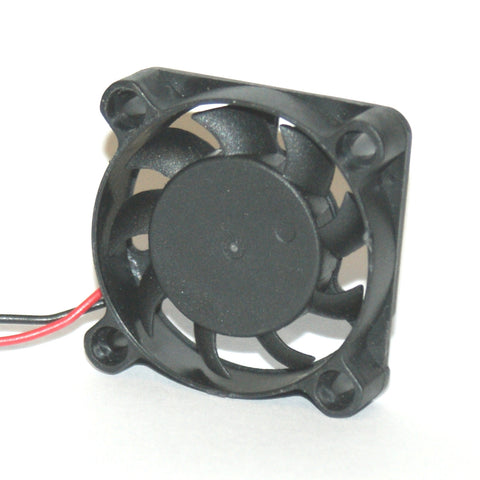
40mm Fan, 5.75 CFM
$ 2.50
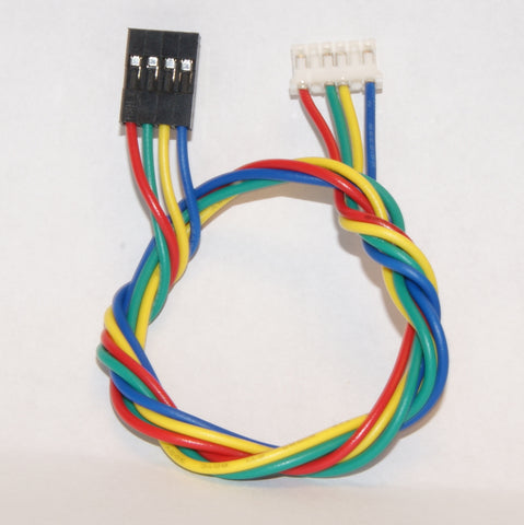
Wire Harness, 750mm (Motor 1124141/1124140)
Wire Harness, 305mm (Motor 1124141/1124140)
$ 1.65